
Please let us know if you have any questions or comments
Operating Instructions
Dear Customer, Before you put the leak detector into operation, please read the following pages carefully and familiarise yourself with how the unit is operated and the additional details. In line with our policy of continuous product development, we reserve the right to alter specifications without prior notice and without regard to the technical status of units already delivered. The illustrations and descriptions may therefore vary from the unit supplied. GEESEN MESSGERÄTE GmbH Mootzenstrasse 24 26683 Saterland / Ramsloh Germany
1.1 General information
1.1.1 Intended purpose
The HG 4 leak detector is designed for detecting with centimetre accuracy leaks in flat roofs constructed with electrically non-conductive insulation materials. The unit is suitable for locating leaks on roofs where the insulation is on the inside or outside. As a rule, it is not necessary to remove stone chippings or other finishes. Furthermore, ponds and swimming pools lined with plastic sheeting and the like can also be inspected for leaks.
1.2 Specifications
1.2.1 Dimensions and weight
Outer dimensions without drums L x W x H in mm: 390 x 210 x 175 Weight complete with drums: 15 kg
1.2.2 Versions
HG 4/1 Power supply 110-125 V, 50-60 Hz HG 4/2 Power supply 220-240 V, 50-60 Hz HG 4/A Power supply 110-240 V, 50-60 Hz with automatic mains adaptor HG 4/B Battery-operated with built-in rechargeable battery Output voltage: approx. 40 V pulse every three seconds.
1.2.3 Power supply
The power supply must correspond to the type of unit. Furthermore, the power supply must be fitted with a proper earth lead.
1.2.4 Operational safety
The unit must not be opened or repaired by unqualified persons without the manufacturer´s permission. Rating plates and labels must not be removed or changed. Failure to observe these rules will invalidate the guarantee and permission to use the equipment.
1.2.5 Storage
When not in use, the unit should be stored in a dry room.
1.2.6 Guarantee
The leak detector type HG 4 is guaranteed against manufacturing defects for 12 months from the date of delivery.
2.1 Description of the unit
2.1.1 Method of functioning
The HG 4 pulse generator emits pulses with a voltage of 40 V. These pulses are transmitted to the roof structure. Since most roofs have a connection to the earth, and the pulse generator is earthed via the power cable (earthing contact), the positive terminal is only connected to the unit via the earthing socket, and the negative terminal is connected to a cable loop laid out on the roof. We now have the positive terminal on the roof (concrete, trapezoidal metal sheets etc.) and the negative terminal on the cable loop. Since every roof covering is more or less non-conductive, the current pulse looks for the path to the leak via the moisture and then flows over the wet roof in all directions to the cable loop. The HG 4 receiver then measures the current´s direction of flow on the roof and thus detects the point from which it originates. This point of origin is precisely the place where moisture is penetrating the roof covering. For this purpose the roof must always be wet, but the moisture does not have to be spread uniformly, nor does it matter if the roof is covered with stone chippings, paving stones or a roof garden. Even a layer of unreinforced concrete above the insulation presents no problem.
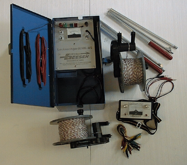
2.1.2 Overview of the components (Fig. 1)
The HG 4 leak detector consists of the following parts:  * Carrying case with built-in pulse generator * Pulse receiver * 2 measuring rods which can be dismantled into 3 parts (total length: 1.00 m) * Various connecting cables * Two drums with cable loop (each 250 m) * Battery charger for the HG 4/B battery-operated unit
2.1.3 Controls
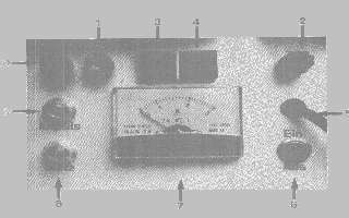
Pulse generator: (Fig. 2) 
1 Earthing socket (not with battery-operated unit)
2 Negative socket
3 Green pilot lamp for the pulse
4 Red pilot lamp for the power supply
5 Power supply cable (charging connection socket for HG 4/B)
6 On/Off toggle switch (HG 4/A has a pushbutton)
7 Ammeter
8 Automatic circuit-breaker for power supply (HG 4/B has battery-charge warning button)
9 Automatic circuit-breaker for the pulse
10 Positive socket
2.1.4 Components
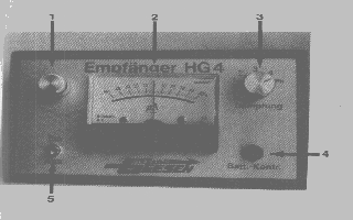
Pulse receiver: (Fig. 3) 
1 Setting controller
2 Display instrument
3 Step switch for attenuation
4 Battery-check pushbutton
5 On/Off toggle switch One red and one black socket are located on the sides for connecting the measuring rods
2.2 Before putting into operation:
2.2.1 Battery check with pulse receiver:
To ensure that the receiver functions reliably, the unit´s battery (9V PP3) must be checked before the unit is operated: Put the toggle switch to the OFF position. Press the Batt. Check button to display the state of the battery. The pointer on the measuring instrument must swing all the way to the left. If this does not happen the battery must be changed.
2.2.2 Displays on the pulse generator:
After connecting the power cable, the red pilot lamp must light up. Then, when the power switch is put to ON, the green pilot lamp must flash with a frequency of one pulse every three seconds.
2.2.3 Functional testing of both units:
Turn the rotary switch on the pulse receiver to the PR position. Connect the red and black sockets on the receiver to the red and black sockets on the pulse generator using the instrument leads and switch on both units. The pointer on the pulse generator must swing to the right in the rhythm of the pulses (green lamp). Now swap over the instrument leads on the receiver; the pointer now swings to the left.
3.1 Preparatory work:
3.1.1 Arranging the cable loop
![[Image]](pict0.gif)
Before starting the measurement, the cable loop must be laid around the roof area which is to be examined. To make it easier to place the cable loop in stone chippings or a similar finish, proceed as follows. Insert the end of the cable loop into the notch at the tip of the measuring rod. Hold the drum with one hand and, with the other hand, push the cable loop under the stone chippings with the aid of one measuring rod. Then connect the two ends of the circuit together. Unearthed metal plates at the raised edges of the roof can also be connected as part of the cable loop, but they must be connected with the roof surface or finish. Earthed metal plates which are connected with the roof finish must be exposed so that the roof surface is visible. On roofs where the roof covering is fixed mechanically (without any finish) the cable loop must be laid out and, if necessary, fixed down with stones, adhesive tape or the like to ensure that it remains in place. If the roof has a thicker finish of earth, humus, swelling clay etc. (intensive covering with grass), it is generally sufficient to press the cable loop as deep as possible into the finish using the measuring rod at intervals of ½ - 1 m. The roofing must, however, be folded up or exposed so that it is visible. If the roof covering is laid in a recess, the finish must be separated from the surrounding soil by digging a trench (see sketch).
3.1.2 Connecting the pulse generator
The red positive socket of the pulse generator must be connected to the green earthing socket by means of the shorting plug. The black negative socket must be connected to the cable loop by means of the black connection lead.
3.1.3 Pulse receiver
Screw together the two measuring rods and connect one rod to the red socket of the receiver with the red instrument lead, and the other rod to the black socket with the black lead.
4.1 Locating the leak
4.1.1 Procedure
Switch on pulse generator and receiver. Position the two measuring rods approx. 1.5 m apart on the roof surface, and as far as possible parallel to the cable loop. The pulses are now shown on the display instrument. Interference voltages (battery effect caused by dirt, minerals etc.) often occur and, owing to the sensitivity of the receiver, they also cause the pointer to swing, but not in a pulsed manner. If this swing is too large, the pointer can be moved towards the middle by using the setting controller. For this reason it is also advisable to leave the rods in position until such time as the pulse is recognised unambiguously. What is important for the measurement is not the size of the pointer swing, but only the direction of swing.This is the direction in which the leak is located. Continue the search in this direction by repositioning both rods. Continue this way until the pointer swings to the other side for the first time. At this point turn through 90° and measure in a direction perpendicular to the first line.
4.1.2 During the measurement
During the measurement it is important to note that everything that is earthed is also displayed through the earthing of the positive terminal. This means that the operator is guided by the measuring instrument, e.g. to a lightning conductor which is in contact with the roof finish. To prevent this, one can either interrupt the connection between the earthed parts and the roof (e.g. by raising up or by placing an insulating sheet underneath), or the earthing of the objects in question can be interrupted (e.g. by disconnecting the lightning conductor). Earthed parts such as metal gutters and drains or the like can be screened off.
4.1.3 Screening
If insulation or interruption of the earthing is not possible, e.g. with drains, ventilation shafts or the like, these objects can also be screened off for this purpose, a cable loop must be laid round the object (if necessary several times). This loop must be connected to the main cable loop, but must not have any contact with the metal. By this method leaks which have already been found can also be screened off in order to continue searching for other leaks if it is not possible to carry out an immediate repair.
4.1.4 Display of the electric field
If the swing of the pointer becomes weaker, so leading the operator approximately towards the centre of the area enclosed by the cable loop (1), this probably means that there are no more leaks. To check this, a piece of cable loop (3), which is connected to the main circuit, must be laid approx. 1 m from the measured point. If this point then moves away from the positioned loop (towards 2), the roof has no leak. Example diagram: ![[Image]](pict1.gif)
4.1.5 Searching for leaks on a roof where the insulation is on the inside (timber construction)
Since a timber construction is not conductive, the procedure is somewhat different. Carry out the preparations described in 3.1. Then connect the red power cable to the red positive socket. Connect the other end (crocodile clip) in the inside area at the place where the moisture escapes (if necessary knock in a nail). If there are drips at several points, it is advisable to connect these points to a piece of the cable loop and then connect to the positive lead. It is also possible to earth the individual wet points to the earthing contact of a power socket or the like by connecting them with a water pipe. If this is done, connection to the positive terminal is no longer required, but the shorting plug on the pulse generator must still be plugged in. Carry out the measurement as described in 4.1.1.
5.1.1 Checking the raised edge of the roof:
![[Image]](pict2.gif)
Pull the cable loop (1) to the middle so that there is still contact at both corners. Place the measuring rods along the edge in longitudinal direction. If the operator is led to the middle from both sides, it can be assumed that there is no leak. To play safe, the position of the cable loop can now be changed from (1) to (2). If the position displayed moves towards the right, for example towards the middle of the curve (2) there is no leak on the raised edge.
5.1.2 Checking the roof drain:
To check roof drains (plastic), proceed as follows: First push the cable loop as deep as possible into the drainpipe so that the cable is in contact with the wall of the pipe. Place one measuring rod on the edge of the drain and insert the second rod into the drain. Then carry out measurement in the same way as on the roof (4.1.1), but with only a small distance between the rods. If the roof drain is free of leaks, the leak detector will guide the operator away from the drain.
5.1.3 Checking of swimming pools:
(non-conductive lining) In swimming pools the floor surface must be measured first. After checking the floor, the walls can then be tested for leaks one after the other, by securing the cable loop with adhesive strips. Ponds lined with plastic sheet can also be checked by placing a cable loop on the outer edge. However, the lining sheet must be exposed so that it is visible. The measurement is made in the same way as on a roof (4.1.1). It must be ensured there is adequate moisture during the measurement.
6.1.1 Measures required in the case of prolonged dryness:
If there is a prolonged period of dryness, the roof finish must be prepared for measurement by copious watering. On roofs with no finish it is sufficient to apply a film of moisture, but this must cover the entire surface. In the case of roofs where the insulation is on the inside a certain waiting time is necessary.
6.1.2 Earthed metal parts:
To establish whether metal parts on the roof are earthed, the cable loop (which is connected to the pulse generator, and the generator is switched on) must be held briefly against the metal. If a whistling signal is heard and the ammeter swings a full deflection, the part is earthed.
6.1.3 Faults
Red pilot lamp does not light up: Check the power supply; automatic circuit-breaker for the power supply has triggered;
Green pilot lamp does not flash:
Unit is not switched on; automatic circuit-breaker for the pulse has triggered;Display instrument on the pulse receiver does not indicate full voltage during battery test:
Incorrect switch setting; battery is too weak;Display instrument on the pulse receiver does not deflect during measurement:
Attenuation is set too high; roof finish is too dry; earth lead of the power supply on the pulse generator is missing;Display instrument on the pulse generator indicates high current value (above 2 A) and a whistling signal is heard:
Cable loop is connected with earthed metal parts; roof insulation is conductive (e.g. owing to very high proportion of carbon black in the rubber covering);7. HG4/B leak detector
7.1 General information
This section describes the special features and differences of the HG4/B leak detector. Measurement itself is carried out in the same way as with the mains-operated unit (see Item 4.1.1)
7.2 Intended purpose
The HG 4/B leak detector is designed for battery-operated use and permits leak detection on flat roofs where no power supply is available nearby.
7.3 Specifications
The HG 4/B leak detector operates with a built-in, rechargeable battery and a battery charger is provided with it. The charge level of the battery is indicated by three LEDs when the Batt. Check button is pressed. The HG 4/B operates for approx. 6 to 30 hours on a single charge, depending on the load. It is advisable to recharge the battery after every use.
7.4 Charging the battery
To charge the built-in battery, proceed as follows: Connect the charging plug of the battery charger to the charging socket on the HG 4/B, and plug the battery charger into the mains supply. Charging takes approx. 10 hours.
7.5 Special features
Since the HG 4/B leak detector does not have an earthed power connection, the positive terminal must be earthed by connecting the red connection lead to a lightning conductor, water pipe or the like.